Tuesday, February 24, 2015

Using Autocad solids versus Revit for a residential house

In New Zealand we have these styles of houses called "California Bungalows".  They were fashionable around 1920 or so.  Their characteristics are: Wooden framing, wooden weatherboards, wooden windows and a corrugated iron roof.  They usually had a bow window.

Here is an example:


I have "happened" on a set of plans which were about extending one of these, and used it to sharpen my Revit skills. Confirmation that Autocad would be a silly way of doing one of these houses would require the same house to be drawn in Autocad solids.

In the Autocad process I found it necessary to draw 14 different but similar windows to suit the various sizes needed.  This seemed to take forever, even using my special lisp routine to draw wooden windows automatically.  It would have taken a lot longer manually doing them from scratch.

You can catch a video of this here: https://www.youtube.com/watch?v=AMLeBgPqOqs

Of course you end up cutting and stretching similar ones, but it is still a lengthy process.

I drew the Autocad one first and then the Revit one second.  Half way through the Revit one I ran out of steam, due to a diversion into the land of families.  I have made several wooden window families, but do not consider myself an expert on these as yet.  For instance: do you make them for one wall thickness or should they adapt to all?  So only a few windows were made.  Half way through this process I realised I should be using "nested families".  This is where you make a sash that fits in several windows.  Again, this is a lengthy process, and full of learning curves.

Here is the Autocad house:


Straight away you can see that there are no materials applied (but they could be).

Here is the same house in Revit:

Here you can see the outer cladding is showing up, as is the "tin" roof. 

With the Autocad drawing the best way to approach the floor plan is to xref the model into a completely new file, and issue the SECTION  command. Here are the results of doing that:


This is just a screen shot (built into Autocad but not revit-all my Revit pics here are using the Windows Snipping Tool).

The Revit one is automatic and looks like this:
This looks a bit more up market than the Autocad one- I would have had to  add doors manually in the Autocad one. Score 1 here for Revit.

Now we get into the "symbolic lines" thing of Revit.  As I understand it, you can draw a window family in Revit, and only bits of it will come out in a plan view.  The reason for this is performance, and at a 1:50 scale is there any point in getting excited?

Here is an Autocad window section:


As you can see, all the solids are shown realistically.

This is a Revit window section, one which I did not add symbolic lines to:


I can hear someone saying, "Ah yes, but you can add these symbolic lines to the window family!"
Well, yes you can, but make sure that they are all constrained and locked, otherwise they go all over the place.  I am tempted to say "Score 1" for Autocad here.

Sectional views:

Here is the Autocad one:


Not pretty, but mostly there.

The Revit one shows the doors, so maybe a score for Revit on this one:

Notice the Revit one has a generic "thick roof", with no purlins shown.  They could have been.  It seems an uphill mission to do a roof with rafters/purlins/tin in Revit.  I am probably doing it the wrong way. The normal way is to probably draw them in using 2D lines.  It is also a pain to do in Autocad, but placement is easier and more precise. The nice thing about doing them in solids is that the roof plan is ready to go.

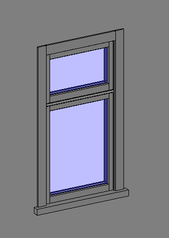
Here is my double sash window: 


I am quite pleased with this, especially the horizontal transom which misbehaved until I struck on the novel idea of locking all the lines together in the outline of the extrusion then having just one locating dimension, as shown in this side view:

This window can cope with user defined sill height, height, width and distance down to the transom from the top.  Making double, treble and quadruple ones can wait until I actually get a job that needs them.

Maybe I am not looking in the right places, but I could not find a Youtube video of transoms with strange profiles, and how to do them. 

Conclusions:

Autocad is a great general drafting/modelling program, of great antiquity (around 1982).  That you can model a house in it speaks volumes for it's versatility.  Revit on the other hand just does buildings, although it can draw things like ovens and range hoods for use as content.

The fact that I had to draw 14 different Autocad windows indicates this could be a time waster on most jobs if you used Autocad.  On the plus side for Autocad is the precision and ease of placing things like rafters and so on.  It has to be said though that Revit's beam system would be the equivalent of this, one which needs practice to get used to coming from an Autocad background.

I have not looked into the automation side of Revit, but no doubt something could be done to produce  a roof that has rafters/purlins/tin all in one hit.

Revit has a very easy to use rendering system, and would score better in production of door and window schedules, especially as any change any where is reflected in all views. In Autocad, you would make changes to your model, then go into the sectional drawing and press the update button on the section tool.

Revit's materials seem to be built in, so concrete comes out hatched in a section as concrete.  To get the same in Autocad you would have to have no hatching in the sectional view and then add concrete hatching manually.

Getting your window content directories full means trips to a site where you have to pay for such things.  One in NZ is: http://www.cadcontent.co.nz/

To sum up then: Revit is a winner over Autocad if you are drawing houses. 


Friday, February 20, 2015

More on Revit Massing

My last post was a bit cryptic, so here is a slightly more verbose version:

You create a Mass family file.  In the creation of the file you have good control over the solids you are drawing and the file I drew ended up looking like this:


A bit grey and bland.  

Then you open a new project and bring in this family.  Then it is just a matter of choosing the Massing & Site tab and picking on say Roof and picking what you want to be a roof etc.

Then it ends up looking like this:


Of course at some stage in a perspective view like this you have to hide in the view the mass, otherwise it shows through as a grey shape under everything. This building shown has been moved on from this stage - it seems architecture might be an iterative process after all?


Monday, February 16, 2015

Revit Massing: It's a wonderful thing

So excited that I actually got something done!

Looking at this series of 3 videos certainly helped.  The only drawback is the audio quality, but the series is easy to understand and copy.

https://www.youtube.com/watch?v=00Uo8gIc1YU

I can imagine the average architect would be impressed by the ease of use of massing.


This all took about 1/2 hour to do.

Time to stop mucking around?

My Revit journey is inching towards something or other.  Namely, a certain level of competence in the use of Revit.

To this end, Robin has kindly lent a book, "Mastering Autodesk Revit Architecture 2011" by Eddy Krygiel, Phil Read and James Vandezande.  A total of 1122 page, and weighs in around 2.3 kg.  Not a complete beginners book it goes into such areas as Film and Stage and Revit in the Cloud , which I am not going study.

Up until now, I have just picked up a project done previously in Autocad and redrawn it in Revit.
While useful, it seems a bit of a disorganised approach.  So I have taken stock of what I do know, and used the headings in the book as a guide for a sequence of study to be undertaken.

This is my list:

1. Advanced modelling and Massing
2. Walls and Curtain Walls
3. Floors, Ceilings and Roofs
4. Family Editor
5. Stairs and Railings
6. Detailing
7. Documentation
8. Annotating
9. Presentation

My present situation is that I threw in my mechanical drafting job on the 19th January 2015, hoping to get a change of scene by drafting houses instead.  This ties in with a desire to work at home, seeing as I have Revit 2015, along with Autocad etc.  I have approached about 8 local architects with an offer of a fixed price per square metre for residential house drafting, but no takers as yet.

Just trolling through other Reviteer's blogs is a depressing journey: I realise how little I know.

Some blogs stand out, this one I like and will be going back to: http://revitrants.blogspot.co.nz/

Just because drawing a wall and inserting a wall is very easy in Revit can lead you into the false idea that this is an easy program to master.


Saturday, February 14, 2015

Is it just me? Or......

I feel a little bit like the old saying: " Ohhh look, there's my Johnny marching with all the other soldiers.  Pity they are out of step except him!"


It seems like nobody on Youtube is drawing truss and frame roofing as we make houses here in
New Zealand.

Another thing is it seems all Revit projects start with the walls. In real life it starts with the site.
Luckily on this project (already built from 2D Autocad drawings) I had access to the surveyors drawings which even had the contours in 3D ready to go.

Interestingly, this import showed the ground levels were slightly out as far as the original drawings were showing. Score One for Revit.

After an unnecessary diversion into Autocad Architecture to use the Drape command and then bringing that into Revit and finding that was not a lot of fun, I used the button marked "Create from Import", and this seemed to work OK.

It seems Revit is so simple to use in the ordinary tasks such as inserting walls doors and windows, but agonisingly difficult in the complicated bits- eg inserting beam systems.  I guess even they will feel straightforward after much use.  Getting the right level or even reference plane is sometimes like a blind man in an unfamiliar room.  Nobody else seems to have these problems.

Still, they might have had proper training!

One little feature I found really cool is if you click on a roof, it becomes transparent, showing the structure below.


Tuesday, February 10, 2015

Beginning Revit, from Autocad

It has been said it is much better to have never touched Autocad before starting Revit.

I have found this to be true, although some things are very similar.

I have made some blunders, as seen below, but I managed to avoid the first one.

This is a pic of  a timber window family, created after much ripping out of hair.

Classic Revit Blunders

1. Want  to have a family, but not quite like the one "out of the box"?
Yup, just go ahead and alter the one that is "out of the box".
This is a classic beginner mistake. ALWAYS Duplicate and name it as something else.

2. Creating new family?  Hmm....where to store it?  Oh look, there are already libraries there,
what a good place to store them.  NOT! Seems like a sensible idea, but if you do a reinstall,
they will get deleted.  Create a new directory somewhere else.  Would it not be nice if
Revit came with a sensibly created directory structure? I like the English way of doing this.

Even then it seems the Revit approach is to lump all things together, then let you sort out what you are after by looking at the name of the file.  So all Aluminium ones are in with the wood.

This seems a very dis-organised approach, so I have created this style of directories, eg,  Components, Doors, Aluminium, Front Doors/Sliding Doors/French Doors/Bifold Doors.  There would be a similar one for Wood.

I see Salesoft (The Auckland New Zealand Revit Reseller) has a set of families for sale,
known as RVT Pacifica, and their naming convention for windows seems to make some sense.

This is an exerpt from their help file:

"All NZ defined Families can be identified by the suffix (NZ) used in the Family file name.
For example: AW 11 Timber-Architrave (NZ).rfa

The Window family Naming Convention used in RVT Pacifica is based on Opening types used in the frame followed by the frame divisions as they are seen from an exterior view and lastly any construction / material description.

The first few characters of the first 'field' denotes the window hung type.
For example…
AW = AWning hung sash window
BF = BiFold hinged unit
BOX = Box Window (under soffit unit)
CA = CAsement hung sash window
CW = Corner Window
DH = Double Hung window
FL = Fixed Lite glass window
GH = Glass House window (glass on top)
LVR = LouVRe window (sash or shutter)
OP = OPening only (no content)
SS = Sliding Sash window
SG = ShugG vertical sliding glass window
TH = Top Hinged sash window

The next 'field' is used to indicate the number of divisions along the frame and the number
of divisions vertically in each of those horizontal divisions.
For example…
  1 = single lite opening
11 = two one lite divisions
12 = two horizontal spaced divisions with 1 lite in the first and two lites in the second

If the window needs to have a specific Left or Right opening designated then the last character
of this field is used to assign which horizontal division has the opening lite. For example…
AW 11R  would be for a two lite with right opening sash.
But usually there is a Flip Control that switches the window around so there is no need for
a specific Left or Right family definition."

(end of help file)

The problem in New Zealand is that we seem to have joinery peculiar to this part of the world.
Even the name is different to the USA: they call it Millwork.

An even larger problem looms with the Master Joiners Federation of New Zealand proposing a
standard set of tested windows, and Revit families of these do not seem to be in existence yet.

The "out of the box" wooden windows available are not exact representations of normal joinery, being very simplified.  Does this matter? Probably depends how fussy you are!